
A primer that walks from the smallest unit — one frame between two devices — up to translation, inspection and proxying. Use this to ground new starters and surface use-cases.
Working in networking and security, I’ve often come back to consider the “best-fit” mechanism for any traffic that passes through a firewall or gateway. To help myself and anyone who’s in the same shoes, I’ve prepared brief notes to help distinguish the concepts. Hope this helps.
Layer 2 – direct addressing on a switch
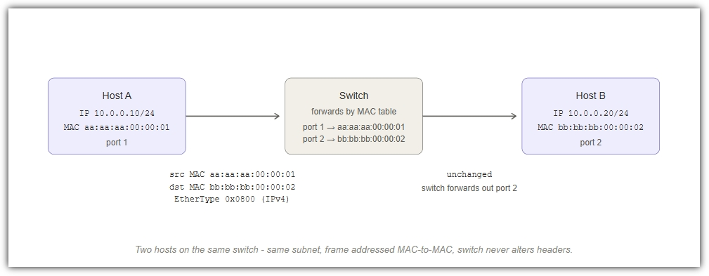
The smallest networking event. Two devices plugged into the same switch talk by addressing each other directly using their physical (MAC) addresses. They may be connected directly or may connect into ports on a switch. The switch is a learning device that forwards frames to the right port based on the destination MAC requested by the data source.
Like two people in the same office room passing a paper note hand to hand. They know each other’s names; the secretary in the middle just passes the note to whoever was named on it.
What’s on the wire
A Layer 2 frame carries: destination MAC, source MAC, an optional VLAN tag (covered later), an EtherType (what protocol is inside – usually IPv4 or IPv6), then the payload.
Broadcast domain
Every host plugged into this switch (or a chain of switches with no router or VLAN boundary in between) shares a single broadcast domain. When Host A doesn’t yet know Host B’s MAC, it sends an ARP request to the broadcast MAC ff:ff:ff:ff:ff:ff, asking “who has 10.0.0.20?” Every device on that broadcast domain hears it; only the one that owns the IP replies. After that, Host A caches the answer and addresses Host B’s MAC directly.
Address Used: Physical address/MAC (48-bit hardware address)
Scope: One broadcast domain (one subnet)
Switch Role: Learns MAC-to-port relationship and stored in a table. Forwards frames based on table.
Discovery: ARP – broadcast “who has this IP?” is answered here with a physical address.
Layer 3 – routed networks without VLANs
Two separate subnets joined by a router. Hosts on different subnets can’t reach each other at Layer 2 – their MAC frames can’t physically cross a router. Instead, each host hands the frame to its local gateway, which forwards the inner IP packet to the next network. The IP addresses stay the same end-to-end; the MAC addresses change at every hop.
Like sending a parcel across town. The parcel label (the IP address) stays the same the whole way. But each courier in the chain (each MAC hop) only carries it to the next handover point.
What changes, what doesn’t
Watch the addresses in the diagram below. The destination IP 192.168.1.20 is set by Host A and stays in the packet header all the way to Host B. But the destination MAC changes at each hop – from the router’s LAN-side MAC, to Host B’s MAC – because MAC addressing only has meaning within a single subnet.
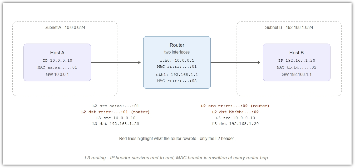
Address Used: IP for end-to-end, MAC for each hop
Boundary: Router separates broadcast domains
L3 Header: Unchanged end-to-end (no NAT here)
L2 Header: Rewritten by every router along the path
VLANs – access ports and trunks
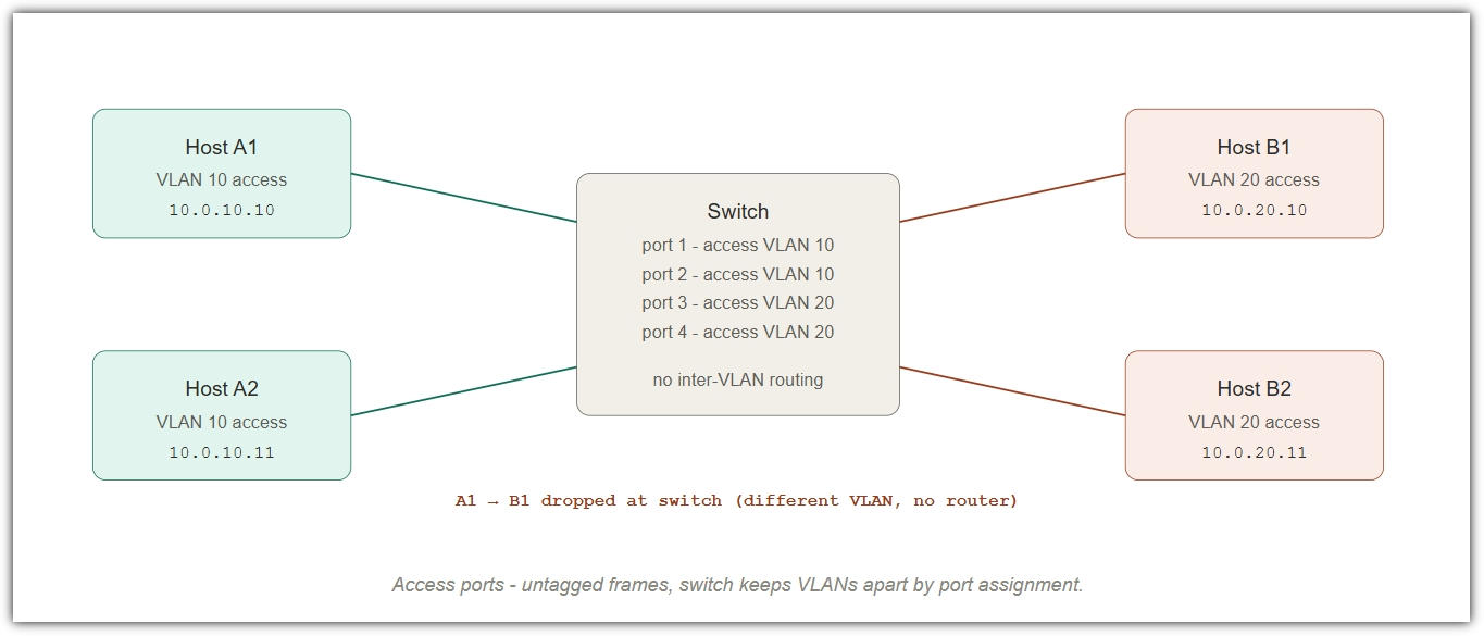
VLANs slice one physical switch into multiple logical switches. Two ports on the same physical switch can sit in completely different broadcast domains. Frames in VLAN 10 can’t reach ports in VLAN 20 – even though they share the silicon – unless a router or L3 switch joins them.
Like a single office building with two companies on the same floor. Same walls, same lifts, but the security pass for Company A doesn’t open Company B’s doors. The only way to move between them is to go through reception (the router).
Access ports – untagged
An access port carries traffic for one VLAN only, and the frames on the wire carry no VLAN tag. The switch knows the VLAN by which port the frame entered. Hosts plugged into access ports are completely unaware that VLANs even exist.
Trunk ports – tagged frames
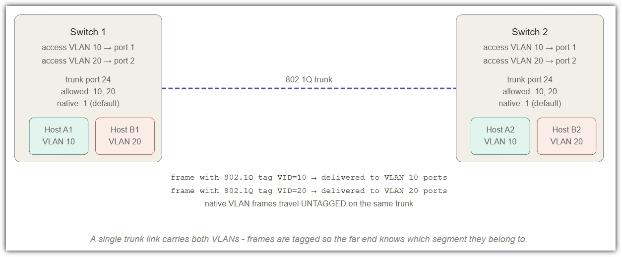
A trunk port (also called a tagged port) carries traffic for multiple VLANs at once. To tell them apart on the wire, each frame gains a small 802.1Q tag – 4 bytes that include the VLAN ID. Trunks are how VLANs extend between switches, between a switch and a router (router-on-a-stick, a separate topic), or between a switch and a virtualisation host that itself runs multiple VLANs.
Many trunk configurations also allow exactly one untagged (native) VLAN on the trunk – frames that arrive with no tag are placed into that one VLAN. This is a common source of misconfiguration: get the native VLAN wrong at one end and traffic silently lands in the wrong segment.
Access port: One VLAN, no tag on the wire
Trunk port: Many VLANs, 802.1Q tag on the wire
Native VLAN: One VLAN per trunk allowed untagged
Inter-VLAN: Needs a router or L3 switch – never done by a plain switch
Common gotcha: a host in VLAN 10 cannot reach a host in VLAN 20 by setting “the right” IP – they are in different broadcast domains.
The packet has to go up to a router that has a foot in both subnets. This is exactly the use-case that drives the next section.
The gateway and the ARP decision
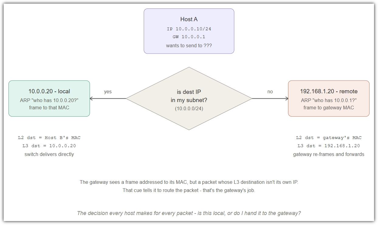
The gateway is the device a host sends traffic to whenever the destination is not on its own subnet. Every host makes the same decision for every packet it sends: “Is this destination on my subnet? If yes, ARP for it directly. If no, send it to my gateway and let the gateway figure it out.”
Like deciding whether to walk down the corridor or hand the parcel to the mailroom. If the recipient is on your floor, you walk. If not, the mailroom handles it from there – you don’t need to know how the parcel gets across town.
The decision a host makes
Given a destination IP, the host applies its own subnet mask to its own IP and to the destination IP. If both produce the same network address, the destination is local; ARP for it. If not, the destination is remote; ARP for the configured gateway instead, then send the frame to the gateway’s MAC.
Why this matters
This is the mechanic that joins L2 and L3. The gateway is just a router (or firewall) that happens to have one foot in your subnet. Hosts don’t “know about the internet” – they only know their own subnet and the address of one device that promises to handle everything else. That’s why a wrong default gateway looks exactly like a connectivity outage even when the switch is fine: the host can ARP locally but has no way to escape its own subnet.
Trigger: Destination IP not in local subnet
What gets ARPed: The gateway’s IP, not the final destination
What’s in the frame: Gateway’s MAC, but the original IP destination
Failure mode: Wrong gateway = looks like an outage
The firewall
A firewall is a router that also enforces policy. Every packet it forwards is also checked against a list of rules – allow this combination of source, destination, port; drop the rest. In its simplest form (stateless), the firewall judges each packet in isolation. In its more common form (stateful – covered briefly below), it tracks connections and lets return traffic through implicitly.
Like reception at a secure office. Same job as the mailroom (forwarding), plus a clipboard of who’s allowed to deliver to whom. If your name’s not on the list for that floor, your parcel goes in the bin.
Stateless rules
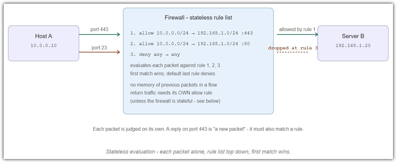
A stateless firewall looks at each packet individually – source IP, destination IP, protocol, ports, interface – and matches it against the rule list. The first matching rule decides the fate of the packet. There’s no memory of what came before; an inbound reply to an outbound request is just another packet that has to match a rule of its own.
What “stateful” adds (preview)
A stateful firewall remembers connections. When Host A opens a TCP session out to Server B, the firewall records the four-tuple (src IP, src port, dst IP, dst port) and notes the state (e.g. SYN_SENT, ESTABLISHED). The return traffic from Server B is recognised as part of that existing connection and let through without needing a matching inbound rule – which is what every modern firewall, including the Sophos UTM230, actually does.
FTP active-mode gotcha. A classic example of stateful firewalls helping and getting in the way. In active-mode FTP the client opens a control session to the server on port 21, then the server opens a brand-new connection back to the client on a high port to deliver data. To the firewall, that inbound data session is a completely new flow with no existing state – and it gets dropped, even though it’s logically part of the same FTP transaction. Stateful firewalls solve this with protocol-aware “connection-tracking helpers” that watch the FTP control channel, learn which high port the server is about to use, and pre-create the matching state entry so the data session is allowed. That is exactly why your UTM230 has FTP and PPTP helpers enabled in Network Protection → Firewall → Advanced – without them, those protocols simply wouldn’t work through the firewall.
Action verbs: allow, drop, reject, log
Match fields: src/dst IP, ports, protocol, interface
Order matters: First match wins; the last rule is usually deny
Return traffic: Implicit if stateful; explicit if stateless
SNAT – specific source NAT
Many internal clients share one specific public IP on the way out. The firewall rewrites the source IP to a fixed external address that you’ve chosen – not the interface address.
Like a building where every outgoing letter gets the company’s PO box stamped on the return address – same PO box every time, regardless of which floor sent it.
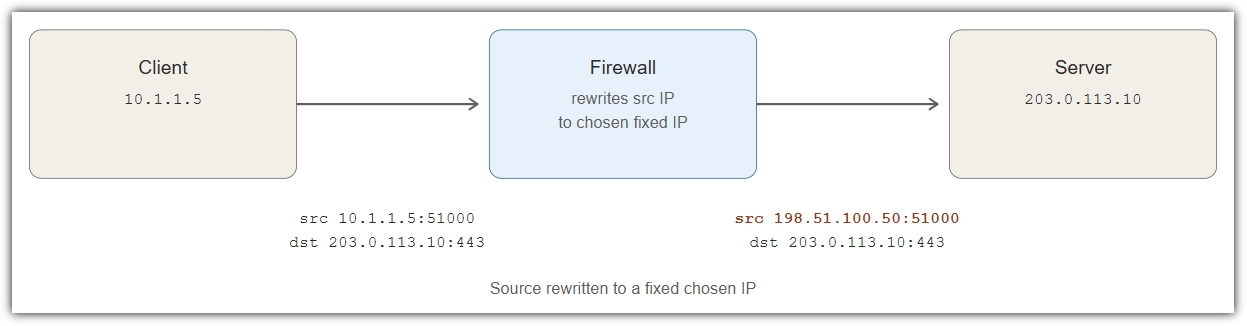
What changes: Source IP (and sometimes port)
Direction: Outbound (internal → external)
Egress IP: Statically configured, not the interface
Server sees: 198.51.100.50 – the SNAT IP
Masquerading
Same as SNAT, except the egress IP is whatever the outbound interface currently has. If the WAN address changes (DHCP, failover, ISP swap), traffic keeps working without any re-config.
Like an outgoing mailroom that stamps the building’s current street address on every outgoing letter – if the business in the building moves, letters automatically get the new address.
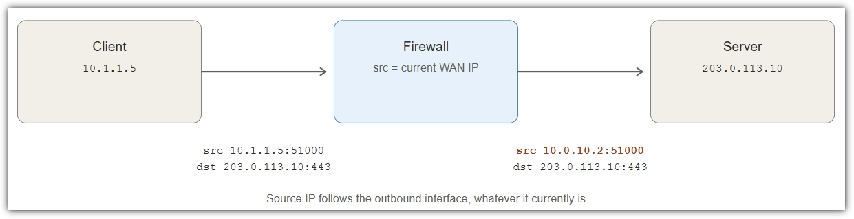
What changes: Source IP (and port if needed)
Direction: Outbound
Egress IP: Whatever the outbound interface holds
Best for: Dynamic WAN, failover, simple LAN-to-internet
DNAT – destination NAT (port-forwarding)
An external client connects to a public IP, and the firewall rewrites the destination to an internal host. This is what people call “port-forwarding”. Source IP stays as the client’s real address.
Like a switchboard receptionist – callers dial one number, the receptionist quietly transfers them to whichever extension actually handles the request, and the caller never learns the extension number.
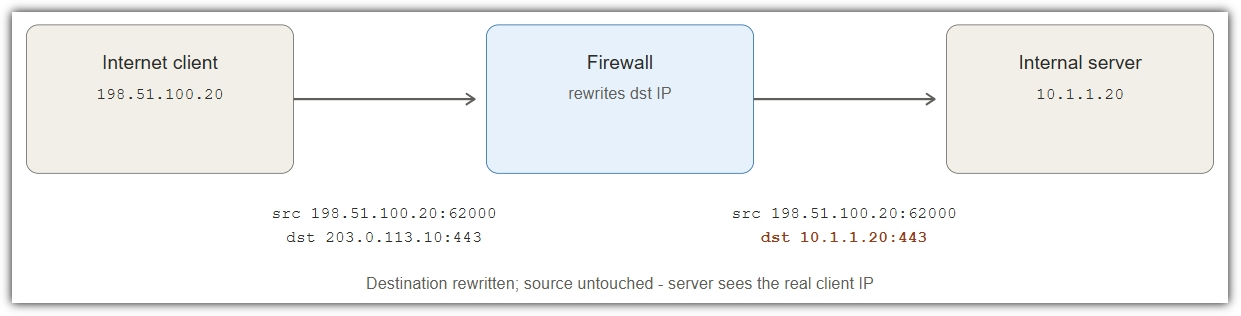
What changes: Destination IP (and often port)
Direction: Inbound (external → internal)
Server sees: Real client IP – useful for logs/ACLs
Common use: Publishing internal services to the internet
Full NAT – source and destination together
Both source and destination get rewritten in the same flow. Used to fix the “hairpin” problem (internal users trying to reach a DNAT-published service), anonymise client IPs to a backend, or steer traffic across asymmetric routing.
Like a courier that rewrites both the sender and recipient labels – the recipient thinks the parcel came from the courier, not from the original sender.
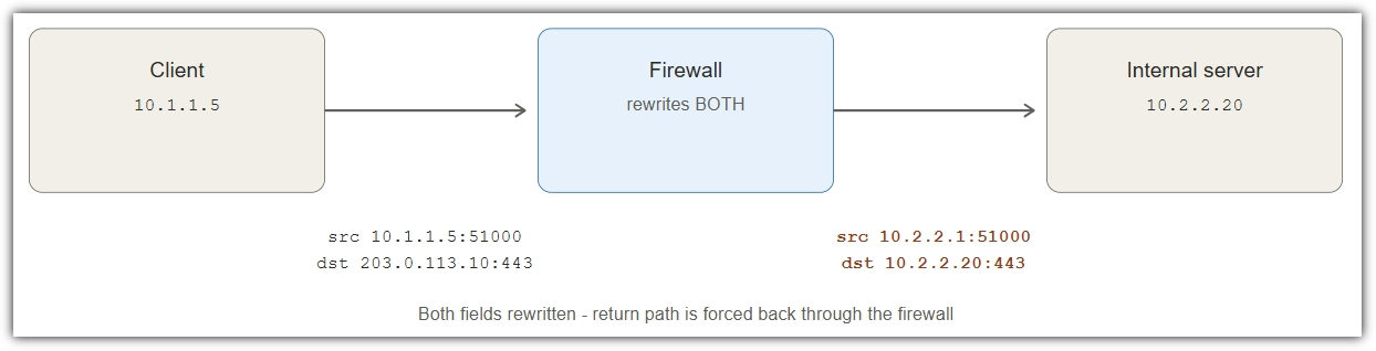
What changes: Source AND destination IP
Direction: Either, often both halves of a flow
Server sees: Firewall IP – real client identity lost
Common use: Hairpin fix, asymmetric routing avoidance
1:1 NAT – static NAT
One public/external IP maps bidirectionally to one private/internal IP. Inbound traffic to the public IP lands on the private host; outbound traffic from the private host appears as that public IP. Symmetric, all-protocol – not port-specific.
Like giving an employee both an internal desk number and a public business card with a direct line – calls in or out always look like that one person at that one card number.
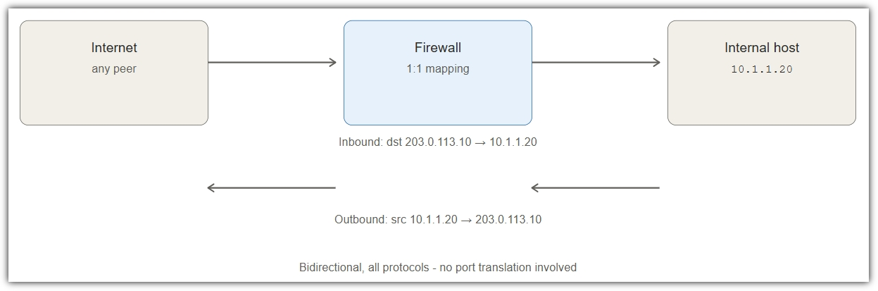
What changes: Whole IP, both directions, no port
Direction: Both – inbound and outbound
Cost: One public IP per internal host
Common use: Servers using non-NAT-friendly protocols
Forward proxy
Not NAT. The client deliberately sends its request to the proxy, which makes a fresh TCP connection to the destination on the client’s behalf. Two separate sessions; the proxy parses the application protocol (HTTP, SOCKS).
Like asking a colleague to phone someone for you – your colleague dials, speaks on your behalf, and relays the reply. The person on the other end never talked to you directly.
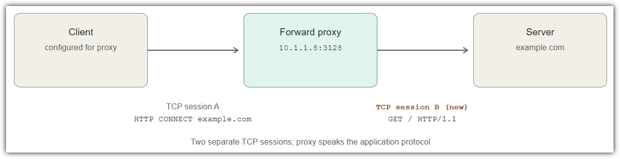
Layer: Application (HTTP, SOCKS) – not packet
Client awareness: Knows about the proxy, configured for it
Sessions: Two separate TCP connections
Common use: Web filtering, caching, content inspection
Reverse proxy
Not NAT. Sits in front of one or more backend servers. External clients connect to the proxy thinking it is the server; the proxy opens its own connections to whichever backend should answer.
Like a hotel concierge – guests ask the concierge for something, and the concierge dispatches whichever staff member is best placed to handle it. Guests never see the back-of-house.
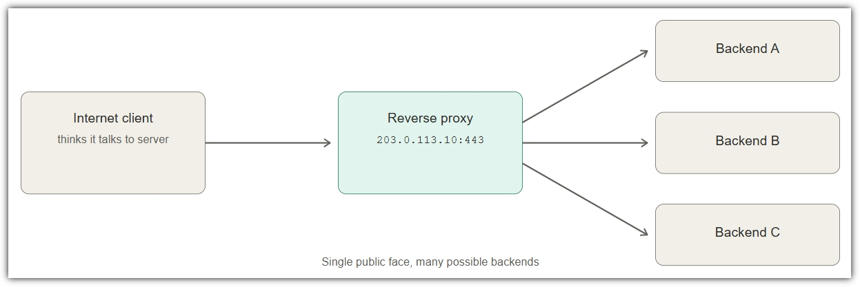
Layer: Application – TLS termination, routing
Client awareness: None – looks like the real server
Sessions: Separate front and back TCP sessions
Common use: Load balancing, WAF, TLS termination
Transparent proxy
A proxy the client doesn’t know about. The firewall silently intercepts the traffic and steers it through the proxy – packets look NAT-like to the client, but underneath, the proxy is parsing (and potentially modifying) the application data.
Like every outgoing letter being quietly opened, read, possibly re-written, and resealed – without the sender ever knowing. Looks like normal post, but isn’t.
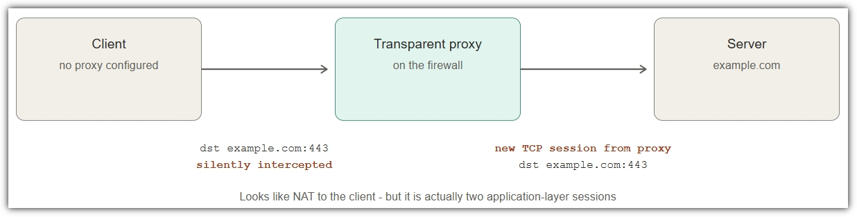
Layer: Application, even though it looks like L3
Client awareness: None – no proxy settings configured
How: Firewall redirects port 80/443 to local proxy
Common use: Web filtering, AV scanning, content rewrite
At a glance
| Technique | Layer | Source IP | Destination IP | Sessions |
|---|---|---|---|---|
| SNAT | L3/L4 | Rewritten (fixed) | Unchanged | One end-to-end |
| Masquerading | L3/L4 | Rewritten (= egress interface) | Unchanged | One end-to-end |
| DNAT | L3/L4 | Unchanged | Rewritten | One end-to-end |
| Full NAT | L3/L4 | Rewritten | Rewritten | One end-to-end |
| 1:1 NAT | L3 | Rewritten (both directions) | Rewritten (both directions) | One end-to-end |
| Forward proxy | Application | Proxy’s IP toward server | Unchanged | Two – client <> proxy, proxy <>server |
| Reverse proxy | Application | Proxy’s IP toward backend | Backend’s IP | Two |
| Transparent proxy | Application (looks like L3) | Proxy’s IP toward server | Unchanged | Two |


Leave a Reply